

How do you calculate the gear ratio in a Planetary Gear set?
You're staring at a complex machine design, and the performance hinges on a compact, high-torque gearbox. The heart of it? A planetary gear set. Understanding its gear ratio is not just academic; it's the key to unlocking efficiency, speed, and torque tailored precisely to your application. So, how do you calculate the gear ratio in a planetary gear set? It's a fundamental question for any engineer, designer, or procurement specialist sourcing components for automation, robotics, or heavy machinery. Getting this calculation wrong means missed performance targets and costly redesigns. This guide breaks down the calculation into simple, actionable steps, showing you not only the "how" but also why partnering with an expert like Raydafon Technology Group Co.,Limited ensures you get the perfect gearing solution for your specific needs, right from the start.
Scenario: You Need a Compact Powerhouse for a Robotic Arm
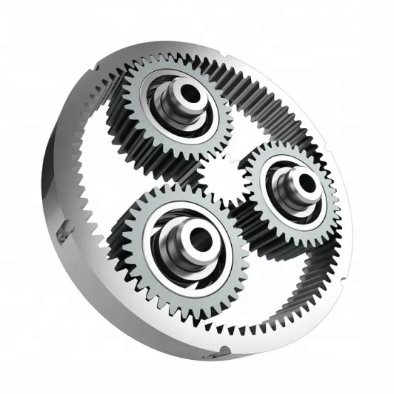
Designing a robotic arm joint requires high torque in a small package with precise speed control. A standard gearbox is too bulky. A planetary gear set offers the ideal solution with its coaxial design and high power density. But selecting the wrong ratio leads to jerky movement or insufficient lifting force. The first step is visualizing the system: a central sun gear, multiple rotating planet gears held by a planet carrier, and an outer ring gear. The gear ratio depends on which component is fixed (stationary), which is the input (driving), and which is the output (driven). For a robotic arm, often the ring gear is fixed, the sun gear is the input, and the planet carrier is the output, providing high torque reduction.
Raydafon's Solution: We don't just sell gears; we provide application engineering. Our team helps you model this exact scenario, ensuring the calculated ratio meets your dynamic load and space constraints. How do you calculate the gear ratio in a planetary gear set? The universal foundation is the Willis equation, which we'll master next.
Mastering the Universal Gear Ratio Formula
The fundamental equation governing all planetary gear sets is the Willis formula: (Ns + Nr) * ωc = Ns * ωs + Nr * ωr. Here, Ns and Nr are the number of teeth on the sun and ring gear respectively, while ω represents the angular velocities of the sun (s), ring (r), and carrier (c). For practical calculation, you use a derived form based on the fixed member. Here is the step-by-step method:
- Identify Components: Determine which part is Fixed (F), Input (IN), and Output (OUT).
- Apply the Standard Ratio Formula: The basic speed ratio is i = 1 + (Nr / Ns).
- Modify Based on Configuration: The actual input-output ratio changes depending on the fixed member. See the table below for common configurations.
For example, with a fixed ring gear (common), input on the sun, and output on the carrier: Gear Ratio (Carrier Output) = 1 + (Nr/Ns). This gives a speed reduction and torque increase. A Raydafon engineer would use advanced software to verify this, accounting for real-world factors like efficiency and backlash, turning a simple calculation into a guaranteed performance specification.
| Fixed Member | Input Member | Output Member | Gear Ratio Formula | Typical Use Case |
|---|---|---|---|---|
| Ring Gear | Sun Gear | Planet Carrier | 1 + (Nr/Ns) | High reduction, high torque (e.g., winches) |
| Sun Gear | Ring Gear | Planet Carrier | 1 + (Ns/Nr) | Moderate reduction, compact size |
| Planet Carrier | Sun Gear | Ring Gear | - (Nr/Ns) | Speed increase, direction reversal |
From Calculation to Specification: Ensuring Real-World Performance
Imagine you're procuring gears for an electric vehicle's axle drive. You've calculated a required ratio of 10:1 for optimal wheel torque. However, the theoretical formula doesn't account for power loss, thermal expansion, or noise generation under load. This is where specification becomes critical. You need to define not just the ratio, but the module, pressure angle, material grade, heat treatment, and precision class (e.g., AGMA or DIN standards).
Raydafon Technology Group Co.,Limited bridges this gap. We provide detailed technical datasheets that map your calculated ratio to a manufacturable, reliable product. Our proprietary design analysis ensures the selected ratio performs under peak load conditions throughout its lifecycle. Consider these extended parameters for a complete specification:
| Key Parameter | Impact on Design | Raydafon's Value-Add |
|---|---|---|
| Gear Ratio & Tolerance | Determines exact output speed/torque; tight tolerance ensures consistency. | Precision manufacturing holds ratios within ±0.5%. |
| Mesh Efficiency (%) | Directly affects power consumption and heat generation. | Optimized tooth profile and finishing achieve >97% per stage. |
| Backlash (arc-min) | Critical for positional accuracy in robotics and CNC. | Customizable control down to <3 arc-min for precision applications. |
| Maximum Torque Capacity (Nm) | Defines the operational limit and safety factor. | Rigorous testing provides certified load ratings for safe operation. |
Expert Q&A: Your Top Questions Answered
Q1: How do you calculate the gear ratio in a planetary gear set when multiple stages are involved?
A: For a multi-stage planetary gearbox (often called a planetary gear train), the overall ratio is the product of the ratios of each individual stage. For instance, if Stage 1 has a ratio of 5:1 and Stage 2 has a ratio of 4:1, the total ratio is 20:1. The key is to correctly identify the input and output for each nested stage. Raydafon specializes in designing such compact, high-ratio gearboxes, managing the complexity so you get a single, optimized unit with a guaranteed overall ratio.
Q2: Does the number of planet gears affect the gear ratio calculation?
A: No, the fundamental gear ratio formula does not depend on the number of planet gears. The number of teeth on the sun (Ns) and ring (Nr) gears are the only factors in the basic speed ratio (i = 1 + Nr/Ns). However, the number of planets is crucial for load distribution, rigidity, and noise. More planets share the load, allowing for higher torque capacity and smoother operation. When you work with Raydafon, our engineers optimize the planet count and layout based on your load requirements, ensuring durability beyond the simple ratio calculation.
Beyond Calculation: Why Your Manufacturing Partner is Critical
Knowing how to calculate the gear ratio is essential, but it's only the first step. The real challenge is transforming that number into a durable, efficient, and cost-effective component that performs 24/7 in the field. Tolerances stack up, materials fatigue, and lubrication fails if not expertly managed. This is where Raydafon Technology Group Co.,Limited delivers unparalleled value. We combine decades of mechanical design expertise with state-of-the-art manufacturing and quality control. For a procurement specialist, this means reduced risk, fewer supplier audits, and a single point of accountability for the entire gearing subsystem. We provide full technical support from prototype to production, ensuring the calculated theoretical performance becomes a reliable reality in your product.
Ready to specify your next planetary gear set with confidence? Contact our engineering team today. Let us handle the complex design validation and manufacturing precision, so you can focus on your core project.


