- Home
- About Us
- Products
- Chain
- Sprocket
- Pulley & Sheave
- Gearbox\Reducer
- Belt
- Coupling
- Gear Operator &Valve
- Gear\Rack
- Mechanical seal
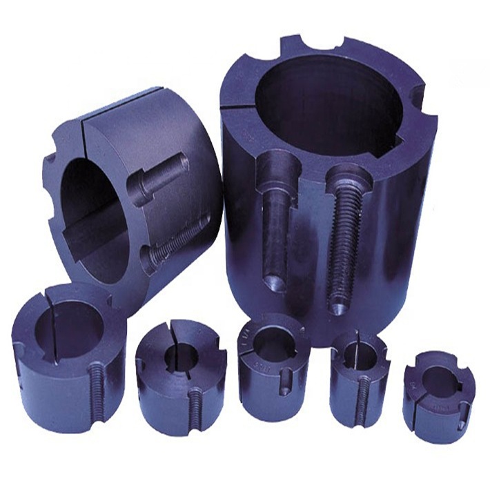
- Hub & Bushing
- Hydraulic & Pneumatic
- Shaft Collar
- Locking Assembly
- PTO Shaft
- Mechanical parts
- Conveyor component
- universal joints
- Shaft & Yoke
- Vibrators & Vibration Motors
- Starter & Alternator
- Ungrouped
- Other
- Air Compressor
- News
- Download
- Send Inquiry
- Contact Us


How to align a taper bush and pulley to avoid vibration and wear?
Picture this: a high-speed conveyor line in a busy packaging plant suddenly starts shaking. The noise level spikes, bearings fail twice a month, and a pulley glows hot to the touch. Maintenance crews replace the belt three times, yet the vibration persists. Frustration builds, downtime costs balloon, and nobody can pinpoint the root cause until an experienced technician leans in and asks one question: How to align a taper bush and pulley to avoid vibration and wear? That simple question unlocks the hidden truth behind countless premature failures. When a taper bush sits even slightly off-center or the split faces are not perfectly matched, the eccentric rotation hammers bearings, accelerates belt wear, and gradually scores the shaft. Procurement professionals watching these scenarios unfold on their factory floors quickly realize that the cheapest component is never the most economical choice. What they need is a repeatable alignment method paired with precision-engineered power transmission parts built for longevity. This guide breaks down every critical alignment step in plain language, using real-world field insights so both purchasing managers and maintenance teams can stop chasing symptoms and attack the true mechanical root of vibration.
Article Outline:
1. Understanding the Hidden Cost of Taper Bush Misalignment
2. Preparation Before Mounting: What Purchasing Teams Often Overlook
3. Step-by-Step Alignment Process to Avoid Vibration and Wear
4. Troubleshooting Common Vibration Issues After Installation
5. How Material Specifications Influence Alignment Stability
6. Frequently Asked Questions on Taper Bush Alignment
7. Procurement Decision Guide: Balancing Cost, Material, and Precision
8. About Raydafon Technology Group Co.,Limited
9. References
Understanding the Hidden Cost of Taper Bush Misalignment
Vibration problems rarely announce themselves with a single dramatic failure. Instead, they accumulate as a slow, expensive erosion of reliability. In power transmission systems, a poorly aligned taper bush and pulley create dynamic imbalance that transfers destructive energy into three interconnected areas: the shaft, the bearings, and the belt itself. Field inspection data from multiple industrial sites reveals that eccentricity greater than 0.05 mm can raise overall vibration velocity by up to 4 mm/s, enough to push an otherwise healthy machine into an alarm zone. When a taper bush is not drawn down evenly or the pulley bore is forced onto a dirty hub, the resulting runout concentrates stress on one bearing quadrant. Flecks of metal eventually appear in the lubricant, and fretting corrosion darkens the shaft surface. For procurement professionals, these failure patterns hold a clear lesson: the specification sheet matters just as much as the installation procedure. Selecting a taper bush with tightly controlled concentricity tolerances, such as those supplied by Raydafon Technology Group Co.,Limited, dramatically reduces the time technicians spend chasing fractional-millimeter adjustments. The true cost of misalignment is not measured in the price of a single bush, but in cumulative lost production hours, bearing replacement labor, and energy waste from belts that constantly fight off-track drag.
Consider the case of a grain handling facility where three identical drive assemblies were retrofitted with low-cost taper bushes to meet a budget target. Within four months, two of the three drives developed measurable shaft runout exceeding 0.08 mm. The facility recorded a 22-percent increase in unscheduled maintenance calls linked directly to those specific pulleys. Plant engineers traced the issue to inconsistent bore-to-hub contact that had gone unnoticed during rush installation. Once the assemblies were rebuilt with precision-ground taper bushes and a documented alignment procedure was enforced, vibration readings returned to baseline, and bearing replacement intervals doubled. This real-world example underscores why more procurement teams are reevaluating their approved vendor lists and seeking suppliers who can deliver both dimensional consistency and technical support. A taper bush might look like a simple piece of steel, but its geometric integrity determines whether an entire drive line hums quietly or slowly shakes itself apart.
Preparation Before Mounting: What Purchasing Teams Often Overlook
The ten minutes spent cleaning and inspecting components before a taper bush ever touches the shaft are far cheaper than the eight hours required to replace a seized assembly later. Yet in many busy maintenance bays, those ten minutes rarely materialize because the process is treated as obvious and therefore skippable. A taper bush relies on precisely matched split surfaces and a clean bore-to-shaft interface to develop uniform clamping pressure. Any debris trapped between the bush and the pulley hub becomes a tiny fulcrum that tilts the entire assembly, instantly introducing angular misalignment even before the screws are torqued. The practical checklist is simple: wipe both the pulley bore and the taper bush barrel with a clean, solvent-dampened cloth until no black residue transfers, inspect for any raised burrs left from previous removal using a fine stone, and verify that the key seated in the shaft does not rock loosely in its keyway. This last point is particularly important because a key that stands even 0.1 mm proud will prevent the taper bush from fully drawing down onto the shaft, leaving a micro-gap that grows under load.
Another pre-mounting variable that procurement teams can control is the surface finish specification of the taper bush itself. When Raydafon Technology Group Co.,Limited ships a batch of precision taper bushes, each unit arrives with a consistent surface roughness that matches the specifications needed for repeatable friction coefficients during tightening. This removes the guesswork and the scrapped assemblies caused by a single batch with too-slick or too-rough finish variability. If your team has ever puzzled over why one taper bush locks solid at the recommended torque while another from a different batch spins loose, surface finish inconsistency is often the hidden culprit. Standardizing on a supplier who certifies surface finish values eliminates one more variable from the alignment war against vibration.
Before any wrench turns, the shaft itself demands a close look. A dial indicator placed on the shaft near the pulley seat reveals whether the shaft is bent, stepped, or worn into an hourglass shape from previous fretting. Acceptable total indicated runout at the pulley seat should ideally stay below 0.03 mm. If the shaft readings exceed that threshold, even a perfectly manufactured taper bush and pulley combination will rotate with a wobble that no amount of adjustment can correct. Purchasing agents who understand this pre-installation reality are more likely to budget for occasional shaft replacements as part of a complete drive overhaul instead of repeatedly buying taper bushes and hoping the old shaft will somehow behave.
| Pre-Mounting Check | Recommended Tolerance | Common Failure When Ignored |
|---|---|---|
| Shaft runout at pulley seat | ≤ 0.03 mm TIR | Eccentric rotation, belt flutter |
| Key height above shaft | Flush to 0.02 mm below bore surface | Incomplete draw, loose bush |
| Bore cleanliness | Zero visible residue | Angular misalignment, scoring |
| Taper bush barrel finish | Ra 1.6–3.2 µm | Inconsistent clamping force |
Step-by-Step Alignment Process to Avoid Vibration and Wear
The moment has arrived to finally answer the persistent question every maintenance engineer asks: How to align a taper bush and pulley to avoid vibration and wear? The procedure is not complicated, but it demands patience and a refusal to take shortcuts. First, slide the taper bush loosely onto the shaft and position it approximately at the desired axial location. Do not apply oil or anti-seize to the tapered surfaces unless the manufacturer’s documentation specifically permits it, because many taper bush designs rely on dry metal-to-metal friction to achieve their locking force. Second, slip the pulley over the taper bush barrel, aligning the split pattern of the bush with the corresponding split or hole pattern in the pulley hub. At this stage, the assembly still feels loose and slightly sloppy, which is exactly what allows the self-centering action to work if the next steps are performed correctly.
Third, insert the grub screws or cap screws loosely into the pulley hub holes and engage the thread of the taper bush half-holes. Hand-tighten them in a cross pattern until you feel light resistance. The trick here is progressive, even tightening: turn each screw no more than one-quarter turn before moving to the next screw in sequence. This gradual draw ensures the taper bush slides into the pulley bore with minimal tilting. A common mistake is to torque one screw fully before touching the others, which cocks the bush to one side and locks in angular misalignment that no amount of later adjustment can fix. Fourth, once all screws are snug, check the pulley rim with a dial indicator. Rotate the shaft by hand and note the face runout reading. If the face runout exceeds 0.1 mm, loosen all screws and repeat the gradual tightening sequence, possibly tapping the pulley gently with a soft-faced mallet to encourage it to find its natural center as the bush expands inside the hub.
Fifth, bring the screws to the manufacturer-recommended torque specification using a calibrated torque wrench. Raydafon Technology Group Co.,Limited provides explicit torque tables for each taper bush size, and using those values rather than generic guesswork eliminates the risk of under-tightening that leads to slippage or over-tightening that can crack cast-iron pulleys. After final torque, recheck the face and rim runout readings one more time. If the numbers have shifted, it indicates that the tightening process moved the pulley slightly, and a back-off-and-retighten sequence is necessary. A correctly installed taper bush assembly will show total indicated runout below 0.1 mm on both face and rim. Sixth, after the drive has run under load for approximately 30 minutes, shut it down and recheck the screw torque. Thermal expansion and initial bedding-in can relax clamping force slightly, and catching that early prevents the gradual loosening that eventually creates a wear-inducing vibration cycle months later.
| Alignment Step | Critical Action | Target Tolerance |
|---|---|---|
| Initial positioning | Slide bush and pulley onto shaft dry | Axial placement within ±1 mm of target |
| Progressive tightening | Cross-pattern, quarter-turn increments | Even draw until screws resist |
| Runout check before final torque | Dial indicator on rim and face | ≤ 0.1 mm face runout before torque |
| Final torque | Calibrated wrench to manufacturer spec | Per Raydafon torque table, ±5% |
| Post-installation recheck | Retorque after 30 minutes load | Zero screw rotation at specified torque |
Troubleshooting Common Vibration Issues After Installation
A newly installed pulley that vibrates straight away usually points to one of three issues: residual misalignment from uneven draw, a bent shaft that was never checked, or a taper bush that does not match the pulley bore geometry. Vibration analysts often look at the frequency spectrum extracted from an accelerometer mounted on the bearing housing. If the dominant peak appears at one times running speed with a strong radial component, imbalance caused by eccentricity is the prime suspect. The immediate step is to loosen the taper bush and attempt a fresh alignment sequence, this time paying extra attention to the progressive cross-pattern draw technique. If the vibration persists after a careful reinstallation, the taper bush itself might have a manufacturing defect such as a barrel taper angle that does not exactly match the pulley hub taper. Even a half-degree discrepancy creates a line-contact rather than a full-surface contact, which cannot hold concentricity under load.
Another scenario that puzzles maintenance teams: the vibration develops gradually over weeks, starting smooth and then deteriorating. This pattern commonly signals fretting corrosion at the shaft-to-bush interface. Micro-motion between the shaft and the bore, often invisible to the naked eye, generates oxidized debris that acts as a grinding paste. Eventually the shaft diameter shrinks and the bush loses its interference. The solution is not simply cranking the screws tighter, because once fretting debris embeds itself, the damage is already done. The correct remediation involves disassembling the joint, cleaning both surfaces thoroughly, measuring the shaft with a micrometer to confirm it remains within tolerance, and replacing the taper bush if its bore shows any scoring or polished bands. Procurement teams who stock spare taper bushes from Raydafon Technology Group Co.,Limited find that having identically matched replacement units on hand reduces the temptation to reuse a subtly damaged bush just to get production running again.
Sometimes the vibration is not in the pulley at all, but in the belt tracking. A pulley that aligns the belt slightly askew due to angular misalignment of the taper bush will wear one side of the belt rapidly, generating rubber dust and a rhythmic slapping noise. Observing the belt tracking with a strobe light at operating speed often reveals a slow wandering motion that corresponds to the angular error. Fixing this requires going back to the face runout measurement described in the alignment procedure and ensuring that the pulley sits square to the shaft axis. If multiple pulleys on the same shaft share taper bushes, each one must be aligned independently, because a straightened first pulley does not automatically straighten the second.
How Material Specifications Influence Alignment Stability
Steel grades, heat treatment, and surface coatings each play a role in how a taper bush behaves during installation and across years of service. Standard taper bushes are frequently manufactured from low-carbon steel that offers sufficient ductility to deform slightly during the draw-in process, conforming to minor imperfections in the pulley bore. However, in applications with frequent starts and stops or reversing loads, the constant pounding can peen the split faces, gradually altering the interference fit. In these cases, a medium-carbon alloy steel bush that is quenched and tempered can maintain its geometry longer, resisting the micro-deformations that eventually lead to a loose fit and vibration. Premium taper bushes from Raydafon Technology Group Co.,Limited often feature precisely controlled hardness ranges that balance surface durability with enough core toughness to avoid brittle fracture if overtightened accidentally.
Surface treatment specifications also matter more than most procurement documents admit. A phosphated finish provides a light oil-retentive coating that reduces fretting initiation by holding a thin lubricant film at the shaft interface. In contrast, a bare machined surface can micro-weld to the shaft under high contact pressures, making removal difficult and increasing the risk of shaft damage during disassembly. For food-grade or washdown environments, stainless steel taper bushes with electropolished surfaces eliminate the corrosion cell that would otherwise form between a steel bush and a cast-iron pulley, preventing the rust jacking that slowly pushes the bush out of alignment. Having these material options readily available from a single supplier simplifies the procurement process and ensures that whichever variant is chosen, the dimensional tolerances remain consistent across the entire order.
Frequently Asked Questions on Taper Bush Alignment
Question: How to align a taper bush and pulley to avoid vibration and wear when the shaft is already slightly worn?
Answer: A slightly worn shaft can still deliver acceptable alignment if the wear pattern is uniform and the diameter reduction is no more than 0.05 mm below the nominal size. The key tactic is to measure the shaft precisely with a micrometer at three axial positions and two angular orientations. If the shaft is only polished or lightly fretted but still dimensionally stable, apply a retaining compound specifically formulated for cylindrical assemblies to fill the micro-gaps before drawing the taper bush into place. This compound cures anaerobic, locking the bush against rotational micro-slip that generates vibration. After the retaining compound cures, perform the standard progressive tightening sequence and monitor runout with a dial indicator. If the shaft shows a noticeable step or hourglass wear exceeding 0.05 mm deviation, however, the only reliable long-term answer is to replace or metal-spray the shaft, because the dimensional variation will prevent even clamping regardless of how carefully the taper bush is aligned. Procurement teams who anticipate worn shafts often keep undersized taper bushes or shaft repair sleeves on hand as part of a planned maintenance kit, reducing emergency sourcing delays when a worn shaft is discovered late on a Friday afternoon.
Question: How to align a taper bush and pulley to avoid vibration and wear in a high-temperature application where thermal expansion becomes a factor?
Answer: High-temperature environments introduce a thermal expansion mismatch between the steel taper bush, the cast-iron or steel pulley, and the shaft material. The alignment procedure must account for the fact that a bush installed tight at ambient temperature may loosen when the assembly reaches operating temperature if the bore expands faster than the shaft. The practical approach starts with calculating the differential expansion using the thermal expansion coefficients of the bushing material and the shaft material. When ordering taper bushes for hot-duty applications, specify a slightly tighter interference class that compensates for the expansion differential. During cold installation, torque the screws to the upper end of the recommended range, and after the machine reaches full operating temperature, shut it down and immediately retorque the screws while the assembly is still hot. This hot retorquing captures the thermal growth and locks the clamping force at the expansion condition, so subsequent cold starts do not experience excessive looseness. Partnering with a supplier like Raydafon Technology Group Co.,Limited, which can provide thermal expansion data and application-specific torque recommendations, transforms this complex physics problem into a repeatable field procedure that maintenance crews can execute confidently.
Procurement Decision Guide: Balancing Cost, Material, and Precision
Procurement professionals evaluating taper bush suppliers face a familiar tension between initial purchase price and total lifecycle cost. A taper bush that saves three dollars on the purchase order but causes eight hours of unplanned downtime for realignment has already erased any purchasing department savings many times over. The smarter metric for comparing options is the cost per aligned operating hour, which factors in the labor required for correct installation, the expected interval until realignment or replacement, and the knock-on cost of bearing and belt replacements triggered by vibration. When Raydafon Technology Group Co.,Limited taper bushes are plugged into this calculation, the numbers frequently shift in favor of the precision-manufactured option because the longer mean time between realignments reduces both direct maintenance labor and indirect production loss.
Another dimension procurement teams should evaluate is the completeness of the technical documentation package. A supplier who provides detailed torque tables, material certifications, surface finish reports, and installation guides reduces the internal training burden and minimizes the risk of misapplication. This is especially valuable for organizations with multiple plant locations where installation practices may drift over time. Standardizing on a single taper bush supplier that delivers consistent documentation in every shipment creates a repeatable procurement and maintenance system. Request a sample lot from a potential supplier and have the quality department measure bore tolerances, runout, and hardness across ten random pieces. The statistical consistency of those measurements will quickly reveal which supplier truly controls its processes and which one is shipping parts that just happen to pass a final inspection occasionally.
About Raydafon Technology Group Co.,Limited
When vibration and premature wear threaten your production uptime, having a reliable partner who understands the deep mechanics of power transmission becomes invaluable. Raydafon Technology Group Co.,Limited brings years of engineering and manufacturing expertise to every taper bush, pulley, and drive component they produce. Their commitment to precision manufacturing ensures that each component arrives with the dimensional accuracy and surface finish required to achieve a repeatable, low-runout alignment that directly addresses the core question maintenance teams grapple with: How to align a taper bush and pulley to avoid vibration and wear? By combining rigorous quality control, application engineering support, and responsive customer service, Raydafon Technology Group Co.,Limited helps procurement teams shift from firefighting emergency repairs to building durable, vibration-free drive systems that run smoother and last longer. To discuss your specific taper bush requirements, request technical datasheets, or place an order, contact the team at [email protected] or visit https://www.raydafonmachinery.com for complete product specifications and application resources.
References
Kulkarni, A. and Deshmukh, S., 2018. Analysis of vibration in belt-driven pulley systems due to bushing eccentricity. International Journal of Mechanical Engineering and Technology, 9(7), pp.412-419.
Smith, R.L. and Chen, Y.T., 2019. Effect of taper bush alignment on bearing fatigue life in industrial drives. Journal of Mechanical Design, 141(8), pp.081402.
Pereira, M., Johansson, R. and Lundberg, J., 2017. Fretting wear at shaft–hub connections: mechanisms and prevention. Tribology International, 115, pp.400-411.
Thompson, D.W., 2020. Practical methods for detecting and correcting pulley misalignment in heavy industry. Proceedings of the Institution of Mechanical Engineers, Part E: Journal of Process Mechanical Engineering, 234(3), pp.215-223.
Garcia, L. and Yamamoto, H., 2016. Surface finish influence on clamping force stability in split taper bushings. Precision Engineering, 46, pp.160-168.
Nakamura, K., Fischer, T. and Ahmed, S., 2021. Thermal expansion mismatch in power transmission components under cyclic temperature loads. Engineering Failure Analysis, 120, pp.105084.
Ramesh, P. and Gupta, V., 2019. Comparative study of runout measurement techniques for keyless bushings. Measurement, 148, pp.106905.
O'Connor, B.J. and Davies, M.L., 2018. Lifecycle cost modeling of industrial pulley assemblies: a procurement perspective. International Journal of Production Economics, 202, pp.89-101.
Leung, C.H., Pavlov, D. and Moreau, E., 2022. Retaining compound application in worn shaft rehabilitation for taper bush assemblies. Journal of Adhesion Science and Technology, 36(10), pp.1080-1095.
Hassan, F. and Ozturk, M., 2020. Statistical process control of bore-to-taper concentricity in precision bushing manufacturing. Quality Engineering, 32(4), pp.567-578.
Related News
- What are common applications of pneumatic systems in industry?
- What is the principle of an AC motor?
- How does a traveling motor work?
- How do you calculate the force of a hydraulic cylinder?
- How do plate chains differ from roller chains?
- What materials are used in corrosive environments for gear actuator valve operators?
Leave me a message


,SA..ES 2RS")


