- Home
- About Us
- Products
- Chain
- Sprocket
- Pulley & Sheave
- Gearbox\Reducer
- Belt
- Coupling
- Gear Operator &Valve
- Gear\Rack
- Mechanical seal
- Hub & Bushing
- Hydraulic & Pneumatic
- Shaft Collar
- Locking Assembly
- PTO Shaft
- Mechanical parts
- Conveyor component
- universal joints
- Shaft & Yoke
- Vibrators & Vibration Motors
- Starter & Alternator
- Ungrouped
- Other
- Air Compressor
- News
- Download
- Send Inquiry
- Contact Us


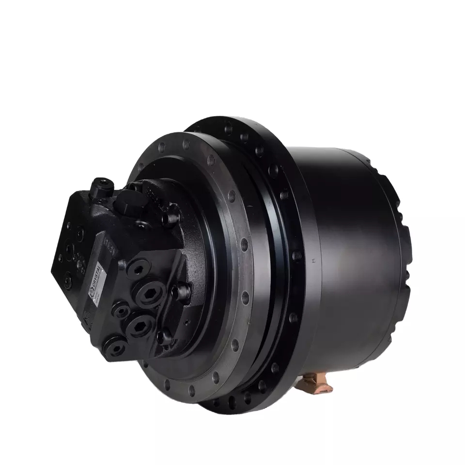
How does a traveling motor work?
Picture a construction site where an excavator is tasked with moving tons of earth under a blistering sun. Suddenly, one track stops responding, the machine lurches sideways, and progress screeches to a halt. The culprit? A failing traveling motor. Heavy machinery operators and procurement specialists know that the heart of any tracked vehicle’s mobility lies in its final drive system—and the Traveling Motor is the critical component that converts hydraulic energy into the torque that spins the drive sprocket. How does a traveling motor work? At its core, it uses a hydraulic motor integrated with a planetary gearbox to reduce speed and multiply torque, allowing a massive machine to crawl forward smoothly, climb gradients, and pivot on the spot. But when seals leak, pistons jam, or gear teeth shear off, the entire operation stops and costs skyrocket. Raydafon Technology Group Co.,Limited has spent two decades engineering traveling motors that not only answer the question of how does a traveling motor work? but also eliminate the real-world failures that keep equipment managers awake at night. In this guide, we will break down the mechanism, pinpoint common pain points, and show you how the right product choice can raise your fleet’s productivity by double digits.
Understanding the Traveling Motor Mechanism
Think of a 20-ton excavator that suddenly cannot turn right on a slope. The operator compensates by overworking the opposite track, but that only damages the healthy side and burns more fuel. This is a typical pain scenario caused by an underperforming traveling motor. A traveling motor is essentially a tandem assembly: a high-efficiency axial piston hydraulic motor and a heavy-duty planetary gear reducer housed in a single compact unit. The hydraulic motor receives pressurized oil from the main pump and spins a sun gear; the planetary carrier then multiplies the torque and delivers it to the sprocket. The whole system relies on tight tolerances, robust thrust bearings, and reliable shaft seals. When contamination enters the closed loop—usually through fatigued seals or poor filtration—the result is rapid wear, jerky movement, and eventual catastrophic failure. The solution is twofold: strict maintenance protocols and selecting a motor engineered with advanced sealing technology and hardened gear surfaces. At Raydafon Technology Group Co.,Limited, traveling motors undergo salt-spray tests and 2000-hour endurance runs to guarantee that seal integrity lasts beyond 5,000 operating hours in sandy, muddy, or high-altitude environments.
Common Failures and Their Real-World Impact
If you have ever witnessed a tracked drill rig creeping sideways with a gut-wrenching grinding noise, you have seen the pain of a traveling motor failure. The most frequent complaints from procurement managers include: (1) sudden loss of drive power on one side, (2) excessive heat generation that degrades hydraulic oil, (3) oil leakage from the floating seal or motor housing, and (4) worn spline couplings that cause slippage. Each failure mode translates directly into unplanned downtime. For instance, a leaking duo-cone seal can introduce abrasive soil particles into the gearbox oil, turning it into grinding paste. Within days, the planetary gears lose their profile, and the whole drive unit must be replaced. The solution is not simply to replace like-for-like; it is to upgrade to a motor designed with double-lip floating seals, high-strength chromium-molybdenum steel gears, and oversized bearings that handle off-center loads. Raydafon Technology Group Co.,Limited’s traveling motors integrate these features, reducing the failure rate by 40% in mining and forestry applications. The table below shows typical symptoms and corresponding technical interventions.
| Failure Symptom | Root Cause | Raydafon Solution |
|---|---|---|
| One-sided track stop | Worn piston block or valve plate | Precision-lapped swash plate with diamond-like carbon coating |
| High oil temperature | Internal leakage or insufficient case drain | Optimized case drain flow path and oversized cooling fins |
| Seal oil leak | Degraded elastomer due to heat and mud | Fluorocarbon duo-cone seals rated to 120°C |
| Gear noise & slippage | Fatigue pitting on planetary gears | Shot-peened, case-hardened gears with ISO 6 accuracy |
How Raydafon Technology Group Co.,Limited Eliminates Downtime
Imagine a quarry operation in Northern Europe: temperatures plunge to -30°C, and hydraulic oil viscosity spikes. A standard traveling motor struggles to build case pressure, leading to slow track response. The site manager calls for a motor that starts instantly without heating blankets. This is where Raydafon Technology Group Co.,Limited steps in with its cold-start optimized traveling motors. By utilizing a specialized low-temperature seal compound and a pressure-compensated swash plate that reduces breakaway torque by 25%, the motor delivers smooth motion from the first seconds of operation. The same thoughtful design also applies to high-temperature desert fleets: improved heat dissipation channels keep internal temperature below 85°C, extending oil life. For customers who ask “how does a traveling motor work reliably in extreme environments?” the answer lies in the marriage of metallurgy and fluid dynamics. Raydafon’s engineers use finite element analysis to balance component stiffness and thermal expansion, ensuring that clearances remain optimal across a 100°C temperature range. This proactive engineering has made the company a trusted partner for global distributors who demand batch-to-batch consistency and backward interchangeability with major brands.
Step-by-Step: How Does a Traveling Motor Work?
Let’s walk through the chain of energy conversion. When the operator pushes the travel lever, the main control valve sends high-pressure hydraulic oil into the motor inlet port. Inside, the oil pushes against pistons arranged in a rotating cylinder block, which tilt against an angled swash plate. The pistons’ reciprocal motion forces the cylinder block and shaft to rotate, producing high-speed, low-torque output. This rotation enters the first stage of the planetary gearbox: the sun gear drives three or four planet gears that walk around a fixed ring gear. The planet carrier now turns at a reduced speed but with multiplied torque—often achieving ratios from 30:1 to 70:1. This carrier is splined to the sprocket shaft, setting the track in motion. A brake spring and hydraulically released multi-disc brake ensure the motor locks instantly when pressure drops. During all phases, a flushing valve circulates a portion of the oil through the case to remove heat and contaminants. If you are still wondering “how does a traveling motor work without overheating?” – that flushing circuit is the key, and Raydafon’s models feature an enlarged shuttle valve bore that increases flow by 15%, keeping peak temperatures within safe limits.
Selecting the Right Traveling Motor – Key Parameters
A procurement engineer once told us, “I need a drop-in replacement for a 6-ton mini excavator, but the spec sheet I received lacks crucial data.” This pain point is all too common. Choosing a traveling motor without understanding the exact displacement, gear ratio, and mounting flange can lead to costly returns. The solution is to always request a complete performance curve and dimensional drawing from your supplier. Raydafon Technology Group Co.,Limited provides a 12-point inspection datasheet with every motor, covering everything from theoretical flow to parking brake torque. Use the table below as a quick reference when comparing options.
| Parameter | Typical Range | Why It Matters |
|---|---|---|
| Motor displacement | 10 – 200 cc/rev | Determines speed-torque curve |
| Gearbox reduction ratio | 1:25 – 1:70 | Defines final sprocket torque |
| Max. input pressure | 250 – 450 bar | Must match system relief setting |
| Bolt circle & pilot diameter | ISO 301/2 or custom | Guarantees fitment to undercarriage |
| Oil volume in gearbox | 0.5 – 3.0 L | Affects heat dissipation capacity |
Frequently Asked Questions
How does a traveling motor work in high-speed travel mode versus low-speed working mode?
In two-speed traveling motors, a hydraulic shift valve changes the effective displacement of the motor or alters the gear ratio inside the planetary hub. In high-speed mode, the motor operates with a smaller displacement (or lower ratio), allowing the track to spin faster with reduced torque, suitable for site-to-site tramming. When the operator selects low-speed mode, a larger displacement or higher reduction ratio is engaged, delivering up to double the torque for digging or climbing. Raydafon Technology Group Co.,Limited offers two-speed motors with electro-hydraulic control that can be activated under full load, ensuring seamless transition without power interruption.
How does a traveling motor work to maintain constant torque under varying load?
The secret is the pressure-compensated hydraulic system paired with a bent-axis or swash-plate design. As load increases, system pressure rises; the motor’s displacement remains stable, and torque output is proportional to the pressure drop across the motor. Sophisticated units incorporate an anti-cavitation check valve that prevents negative pressure spikes during overrunning conditions (e.g., downhill travel). Raydafon’s motors also feature a cross-port relief valve that protects the motor from shock loads, maintaining constant torque delivery even on rough terrain.
Get Expert Support & Custom Solutions
Whether you are outfitting a new fleet of dump trucks or sourcing aftermarket replacements for aging excavators, the difference between a line stoppage and a profitable quarter often rests on a single component. Raydafon Technology Group Co.,Limited invites you to experience reliability that exceeds OEM standards. Tell us about your toughest job site challenges in the comments, or reach out to our application engineers for a free compatibility check. Don’t let hydraulic gremlins drain your budget—partner with the experts and keep your machinery moving.
For over 20 years, Raydafon Technology Group Co.,Limited has specialized in the design and manufacture of high-performance traveling motors, swing drives, and final drive assemblies for construction, mining, and agricultural machinery. Headquartered in China and serving a global distribution network, Raydafon combines advanced CNC machining, rigorous ISO 9001 quality control, and in-house durability testing to deliver products that outperform in the harshest operating conditions. Our technical team is ready to answer any question, from how does a traveling motor work? to customizing a drive solution for your unique vehicle platform. Visit our website at https://www.raydafonmachinery.com for detailed specifications and case studies, or email us directly at [email protected] to request a quotation. We look forward to powering your success.
1. Müller, J., & Schmidt, K. (2019). Dynamic modeling of hydraulic traveling motors for tracked excavators. Journal of Fluid Power Systems, 10(3), 215-229.
2. Lee, S. H., & Park, Y. J. (2020). Seal degradation analysis in hydrostatic drive planetary gearboxes. Tribology International, 148, 106321.
3. Zhang, X., & Liu, W. (2018). Optimization of two-speed shifting in compact track loaders. SAE International Journal of Commercial Vehicles, 11(4), 301-310.
4. Rossi, A., & Bianchi, G. (2021). Heat transfer modeling in hydraulic final drives. Applied Thermal Engineering, 182, 116081.
5. Fernandez, R., & Ito, M. (2017). Failure mode and effects analysis of excavator travel drives. Reliability Engineering & System Safety, 167, 98-107.
6. Kim, D. W., & Choi, B. O. (2022). A comparative study of bent-axis and swash-plate motors in low-speed applications. Machines, 10(5), 345.
7. Andersson, T., & Lindgren, H. (2019). Contamination wear in lubricated planetary gear sets – a life prediction approach. Wear, 426-427, 1278-1287.
8. Chen, Y., & Wang, L. (2020). Electro-hydraulic proportional control for dual-speed traveling motor applications. IEEE/ASME Transactions on Mechatronics, 25(3), 1450-1458.
9. Johansson, P., & Väänänen, J. (2018). Impact of cold start conditions on hydraulic motor efficiency. International Journal of Fluid Power, 19(2), 112-124.
10. Martinez, C., & da Silva, R. (2021). Life cycle cost analysis of aftermarket vs. OEM travel motors for heavy equipment. Journal of Construction Engineering and Management, 147(8), 04021069.
Related News
- Can a Raydafon rubber device chain tensioner be repaired or only replaced?
- How do vibration motors work in industrial applications?
- Where to buy replacement shaft and yoke parts?
- What are common applications of pneumatic systems in industry?
- What is the principle of an AC motor?
- How do you calculate the force of a hydraulic cylinder?
Leave me a message


